Patents
Power Monitor-Glitch Trap System (PM-GT)
Date of Patent: Feb. 20, 2007
Patent Number: 7,180,301 B1
Inventor(s): Mark W. Hynes
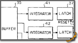
Abstract: A device for sensing and capturing the state of a direct current electrical power line comprising a voltage comparator having a pair of inputs, one of the inputs adapted to be connected to the power line, the other input connected to an analog and digital I/O module for supplying a threshold voltage to the voltage comparator, a plurality of latches, an equal plurality of integrators having different time constants, each integrator connected between the output of the voltage comparator and one of the plurality of latches for supplying an integrated replica of the output from the comparator to the latch, the analog and digital I/O module also being connected to the plurality of latches for reading the states of respective latches and for resetting any set latch, and a programmed computer connected to the analog and digital I/O module for controlling the operation of the analog and digital module and for logging the occurrence of the setting of a latch.
Modular Covert Remote Electronic Warfare Simulator
Date of Patent: Jun. 8, 2004
Patent Number: 6,748,351
Inventor(s): Mark W. Hynes, Robert L. Weeks, James L. Cole, Robert E. Reiner, Timothy T. Taylor
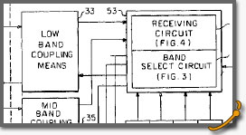
Abstract: An apparatus for electronic warfare signal simulation which is used in an external test system to simultaneously test a plurality of 'victim' communication systems for vulnerability to jamming. The test system includes a remote radiator of a signal free of jamming effects, and a remote radiator of one or more radio frequency control signals which represent one or more predetermined jamming threats in the low and mid bands. The simulation apparatus has a pair of couplers, each adapted to be coupled between a respective one of a plurality of 'victim' antennas and its associated 'victim' receiver, for coupling off the control signals to a receiving circuit, a plurality of modules for generating simulated jamming signals, and a band select circuit for translating the frequency of each simulated jamming signal, setting its level to that determined for its control signal, and replicating the 'victim' antenna gains, and feeding the modified simulated jamming signals together with the desired signal to the plurality of 'victim' receivers.
Apparatus for Providing GPS Positioning Information to a Plurality of Computers from Only One GPS Receiver
Date of Patent: Jan. 6, 2004
Patent Number: 6,674,400 B1
Inventor(s): Mark W. Hynes
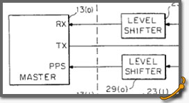
Abstract: An apparatus for providing GPS positioning information to a master computer and a plurality of slave computers from only one GPS receiver. The apparatus includes a circuit adapted to be coupled between the GPS receiver and the computers for providing each computer with a replica of a positioning information signal from the GPS receiver so that each computer receives all of the positioning information it would have received if it had been connected to its own GPS receiver. In addition, the apparatus includes a circuit adapted to be coupled between the GPS receiver and the computers for providing each computer with a replica of a synchronizing signal from the GPS receiver so that each computer receives the synchronizing signal it would have received if it had been connected to its own GPS receiver. Further, the apparatus includes a circuit adapted to be coupled between the GPS receiver and the master computer for passing a control signal from the master computer to the GPS receiver to set up and control the state of the GPS receiver.
GPS Tracker
Date of Patent: Sep. 30, 2003
Patent Number: 6,628,232 B1
Inventor(s): Mark W. Hynes, Barry C. Miller, Mark S. Barrett
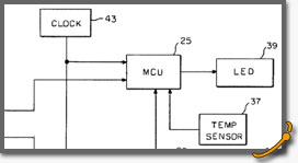
Abstract: A vehicle tracking system that includes a plurality of trackers, each adapted to be attached to a respective movable vehicle, and a remotely located controller for individually polling by radio each of the trackers to determine the position of the polled tracker. Each tracker includes a positioning receiver which receives satellite signals from a Global Positioning System and transmits a first positioning signal containing the position of the tracker to a micro controller unit. The micro controller unit receives the signal and transmits a second positioning signal containing the position of the tracker to a communicator. The communicator radios the second positioning signal to the remotely located controller to communicate the position of the tracker in response to a radioed polling signal from the remotely located controller.
System for Detecting Gunshots
Date of Patent: Feb. 6, 2001
Patent Number: 6,185,153 B1
Inventor(s): Mark W. Hynes, James Lee Cole
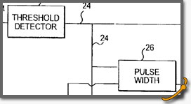
Abstract: A system for detecting gunshots includes an input device including a microphone for converting acoustic noises into signals and amplifiers for amplifying the input signals, a threshold detector for receiving the amplified signals and comparing the signals with a predetermined threshold value and for producing an output signal when the threshold value is exceeded. A pulse width detector is connected to the threshold detector for producing an output signal only if the width of the threshold detector output signal is within a predetermined range of values. A pulse count detector is also connected to the threshold detector for producing an output signal when the level of the threshold output signal is above a peak threshold level or the number of threshold level output signals that exceed a threshold level are less than a preset limit. An output device indicates that a gunshot has occurred only when signals are received from the pulse width detector and the pulse count detector during a sampling period.
System and Method for Performing Jamming Testing on Communication Networks
Date of Patent: Mar. 23, 1999
Patent Number: 5,886,626
Inventor(s): Mark W. Hynes, James L. Cole, Barry C. Miller, Scott A. Morris, Robert E. Reiner
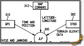
Abstract: A system is tested for jamming resistance by supplying a simulated jamming signal. The simulated jamming signal is produced by calculating a propagation path loss in the terrain between the system under test and a location where the jammer would be, predicting a jamming level in accordance with the propagation path loss, and generating a simulated jamming signal. The simulated jamming signal is supplied to the antenna port of the system under test. The testing does not require the use of either a real jammer or a pilot signal generator at the location where the jammer would be.
Communications Electronic Warfare Trainer
Date of Patent: Dec. 10, 1996
Patent Number: 5,583,509
Inventor(s): Mark W. Hynes, James L. Cole, Garrett W. Conover, Michael J. O'Connor
Abstract: A communications electronic warfare trainer that includes apparatus and a method by which a training umpire can control the localized jamming of a victim communications system. A control signal containing an address and duration of jamming is generated and transmitted using the same frequency as the victim communications system. The control signal is processed by a Receiver Unit collocated with the victim communications system to determine if the control signal address matches the address of the victim communications system. If an address match is found, a jamming signal is produced for the specified duration causing disruption of the normal operation of the victim communications system.
Frequency Analyzer for Sub-Microsecond Testing
Date of Patent: Jan. 16, 1996
Patent Number: 5,485,101
Inventor(s): Mark W. Hynes
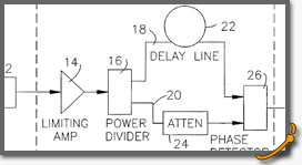
Abstract: A method and apparatus for measuring the settling time of frequency changes in a voltage-controlled oscillator (VCO) are disclosed. A signal splitter is responsive to the VCO for splitting the output signal between first and second channels. A delay circuit in one of the channels introduces a delay and corresponding phase shift of one signal relative to the other, and a phase detector produces a phase signal proportional to the phase shift indicative of the settling time of the VCO. A control circuit coupled to the phase detector and VCO produces a step voltage-initiating signal for changing the VCO output frequency. A detector responsive to the initiating signal and the phase signal produces an output indicative of the settling time with respect to the control signal in the modulation domain.
Covert Remote Electronic Warfare Simulator
Date of Patent: Aug. 23, 1994
Patent Number: 5,341,146
Inventor(s): Michael D. Vennum, Mark W. Hynes, Gary Conover
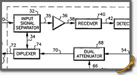
Abstract: A covert remote electronic warfare simulator is disclosed which includes receiving and signal processing apparatus for incorporating various electronic signal parameters and variables representing propagation effects from the environment borne by a low power control signal for redirection from a 'victim' antenna into a 'victim' receiving apparatus. The invention includes methods and apparatus for the subsequent replay of stored data representing the resulting signal(s) for data collection and detailed analysis in a laboratory setting. The simulator apparatus is interconnected between a 'victim' receiving antenna and a 'victim' transceiver to provide a simulated jamming signal.


